
Building a Facit Home
- Feb 26, 2025
- 5 min read
Our highly engineered Facit Chassis™️ is digitally designed and manufactured to meet the highest possible standards of environmental performance.
This latest FSC timber superstructure, for a large family home in North London, is a perfect example of how our intelligently coordinated approach to construction is used to successfully deliver projects with a high level of complexity.

The construction plan.
Digitally manufacturing a Facit Home
After the digital design of this home was finalised by our in-house architects using BIM (Building Information Modelling, our intelligent 3D design software), work began to put the project into production.
Approximately 3 months before we start erecting the chassis on site, our production team specifies every little detail and translates the complex digital design into G code, a computer language that allows us to automate the manufacture of plywood sheets using CNC (computer numerically controlled) machines.

The digital manufacturing of the plywood Facit Chassis™️ components can take place on site or off site, depending on the project.
On site manufacturing involves the delivery of the CNC machine to site in a shipping container. Off site means the manufacture takes place in the London workshop and involves regular deliveries of ready-assembled components in order to site. Each FSC plywood component is unique and numbered accordingly to give an accurate order of installation.
Each component is designed and engineered to guide assembly, with dedicated spaces, channels and compartments for cables, ducts and pipes so that services and products can be installed as work continues to the home. The intelligent installation of the timber structure speeds up the construction phase and reduces time spent on site.
The main stages of Facit Chassis™ construction
Groundworks are completed before the installation of the timber frame Facit Chassis™ begins. At this point, the footprint of the home is just a concrete slab and is ready to be transformed into a contemporary home.
1. Fix sole plates
The first step is to fix sole plates to the concrete slab. Sole plates are timber boards that must be fixed around the perimeter to signal exactly where the ground floor external wall components will be installed. While this is happening, the wall components are delivered to the site ready for installation.


2. External walls
Once delivered, the external walls for the ground floor are fixed onto the sole plates by our team of on site professionals. In order to be load bearing and to make up the thermal envelope of the home, these walls must be perfectly vertical and level.
Timber is a great construction material, but there is sometimes a little bit of deviation (especially with weather exposure) so components are held in place by timber braces until the structure is complete. This is so they remain flush with the sole plates.


3. Internal load bearing walls
To mark progress, the first components installed were signed by our customers. As work progressed, the ground floor components installed started to reveal the shape of the home and the door and window portals. Internal load bearing walls were next to be completed.


4. Steel beams
The steel specified for the ground floor reinforces the structure where necessary. It allowed us to design a three storey home with an open plan ground floor, a large opening for bifold doors and a first floor overhang in one corner.
Before, during and after steel installation, the ground floor headers and beams are installed (see third pic). These are placed on top of the external and internal walls so that the first floor beams can be fixed onto them.
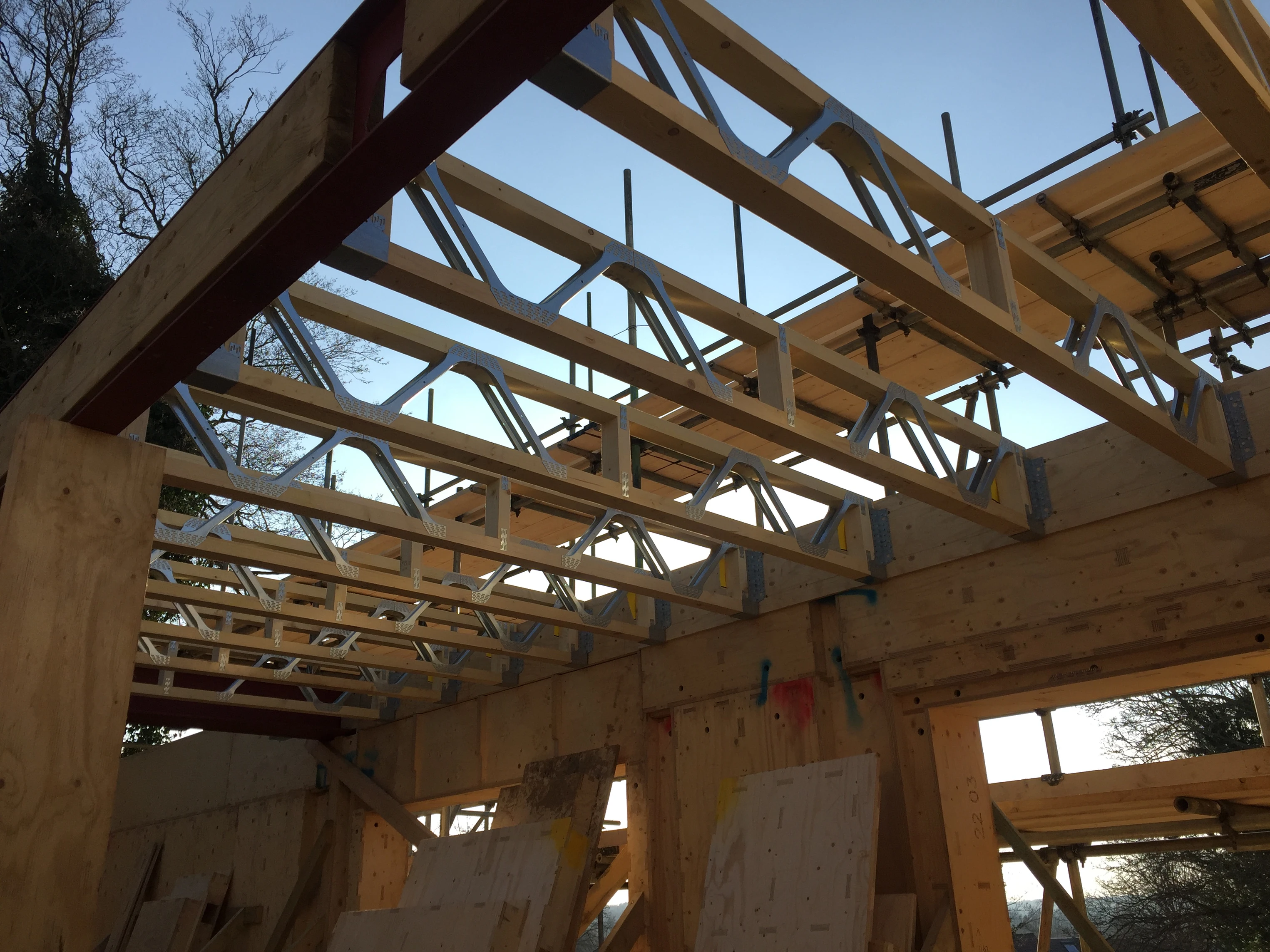
5. First floor install
In order to complete the first floor, scaffolding is required. The scaffolding started to go up as the ground floor was completed. First floor beams were positioned in place by the team and posi joists were installed to create the bare bones of a first floor. Posi joists have metal hangers that allow ductwork and pipes to move through the gaps.
The floor components are always accurately designed to slot neatly between the post joists, so these were dropped into place by the team. A rubber mallet (dubbed "the persuader") can be used if components are stubborn. The floor is complete!


6. Starting again
For the work on the first floor to continue, we started fixing sole plates and external walls. Like layers of a cake, this step-by-step process follows the same system as the ground floor, with internal walls and floor components following suit.
Works often happen to multiple parts of the structure simultaneously. Our rigorous construction programme allows us to be efficient in our use of manufacturing and on site manpower. For example, while the main external envelope of the chassis was going up past the first floor, some of the team kept working on the ground floor installation - in particular, the non-load bearing internal stud walls. Progressing the works to the ground floor and first floor at the same time meant we could maximise output on site.
Digitally manufacturing a roof
In order to maximise the usable space in the top floor of this home, we digitally designed a mansard type roof shape that would allow the maximum amount of full height space on this floor.
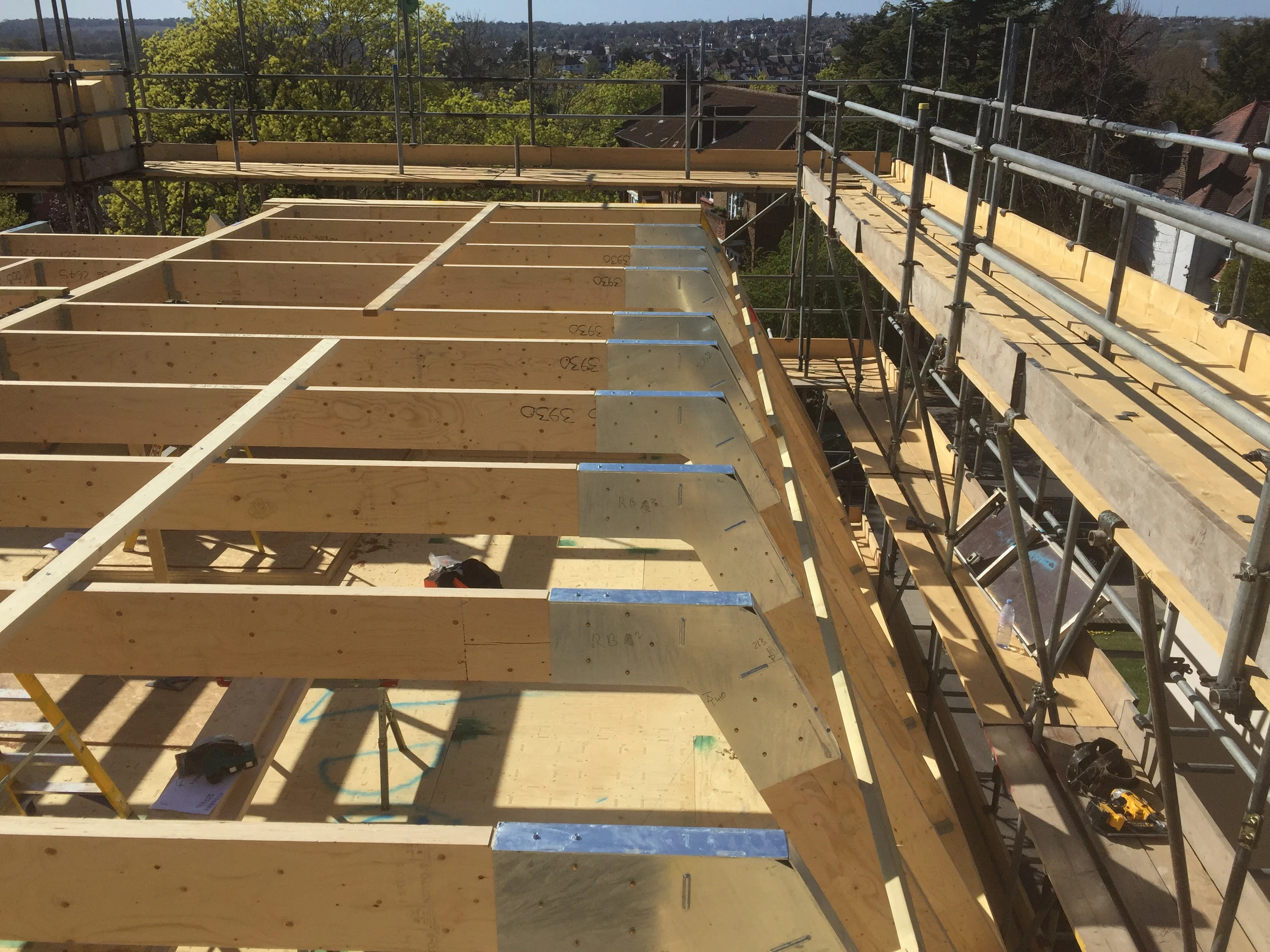
Roof beams
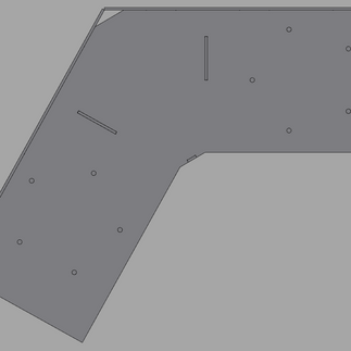
Digital manufacturing roof beams with stiff corners allowed us to do just that. The beams are held in place by unique junction boxes that we digitally fabricated in-house to replace a previously handmade solution. Digitising construction in action!
The laser cut steel sleeve holds the two timber beams in place. These would have otherwise been joined by two loose plates. This digitally manufactured product saves time and reduces complexity on site, plus it is adjustable in our digital model.


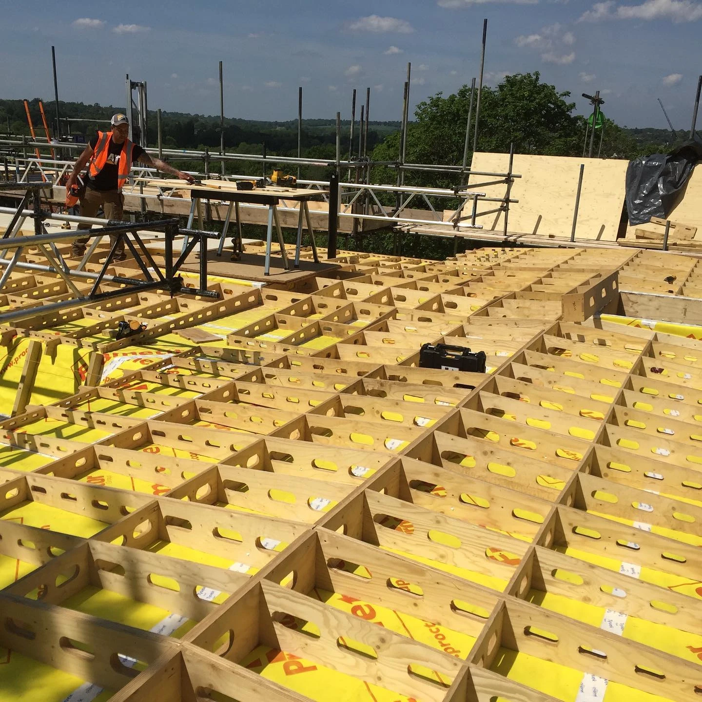
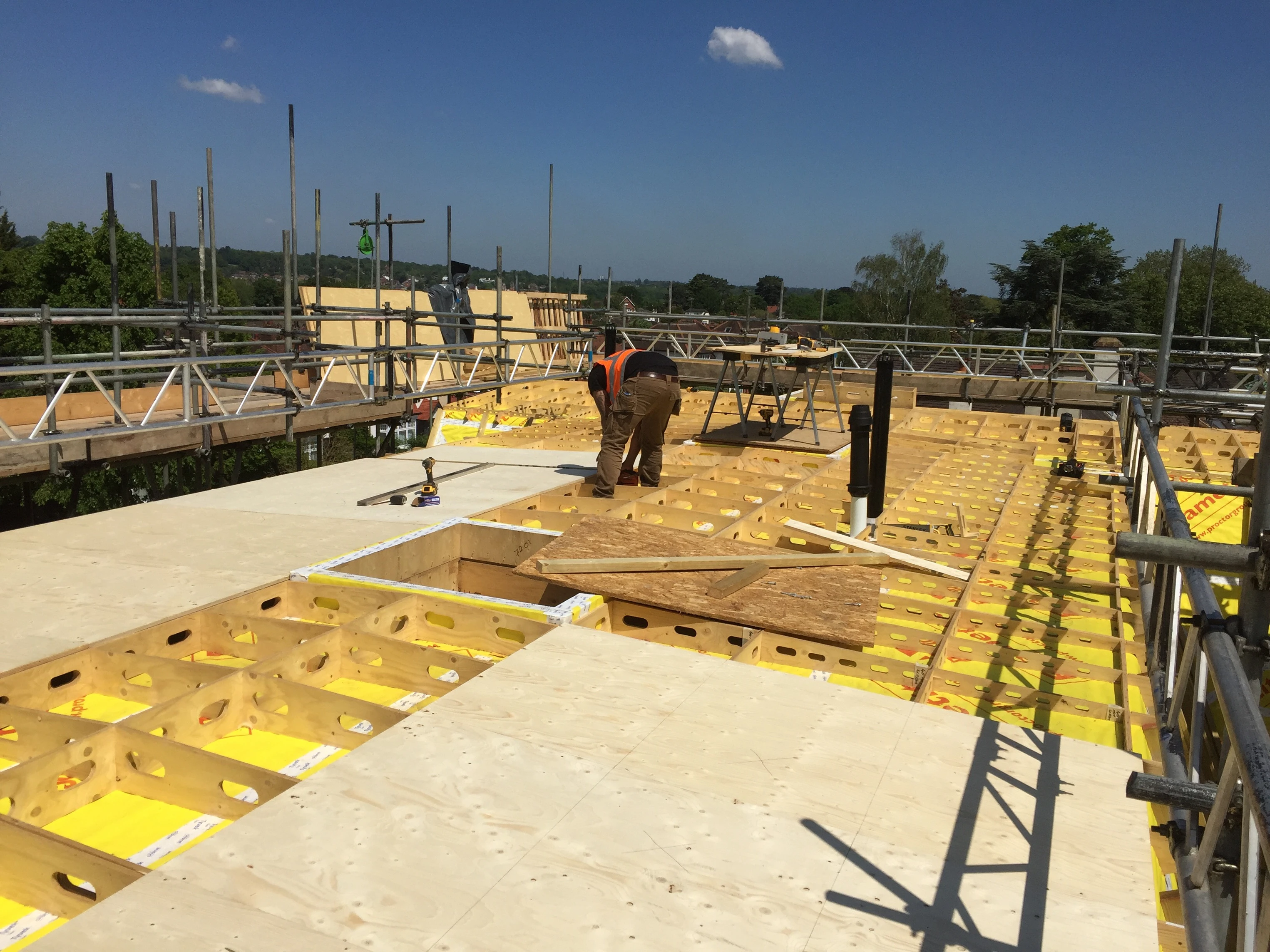
2. Roof components
No need for posi joists in this stage, the roof components are designed to fit within the roof beams and timber studs. The roof had some quite complex geometry going on, especially above the stairs. Digitally manufacturing the home from timber allowed us to create precise and bespoke components to accommodate the unusual geometry.
3. Topping out ceremony
Once the roof beams were in place, we installed the final roof component in a topping out ceremony with our customers to celebrate the milestone.


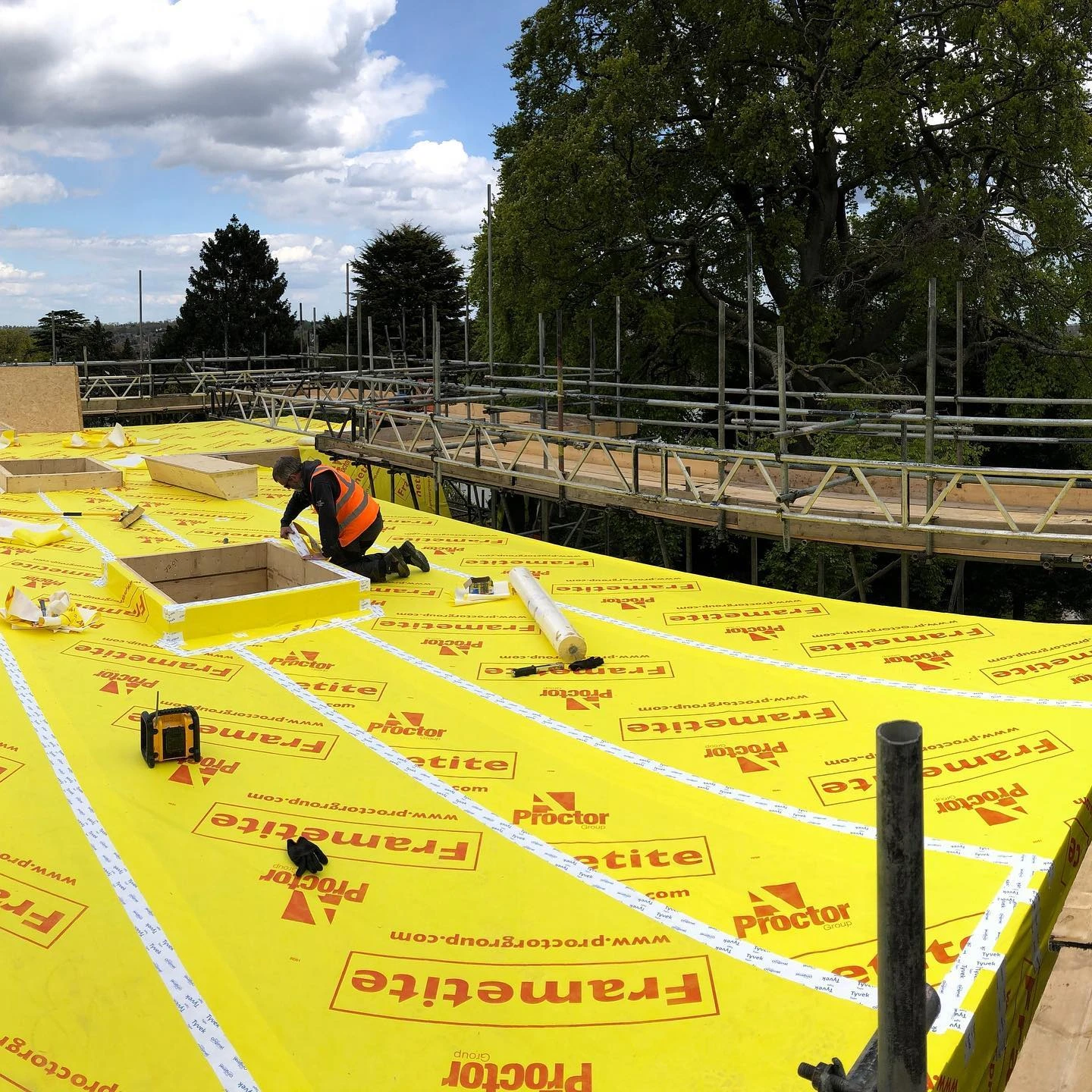
4. Breather membrane
Once the entire Facit Chassis™️ was complete, we wrapped the building in bright yellow Frametite, a breather membrane that ensures the home is both airtight and resistant to condensation. Moisture vapour passes through the layer and can disperse to the outside atmosphere without being cooled, thus eliminating issues such as condensation and mould growth.


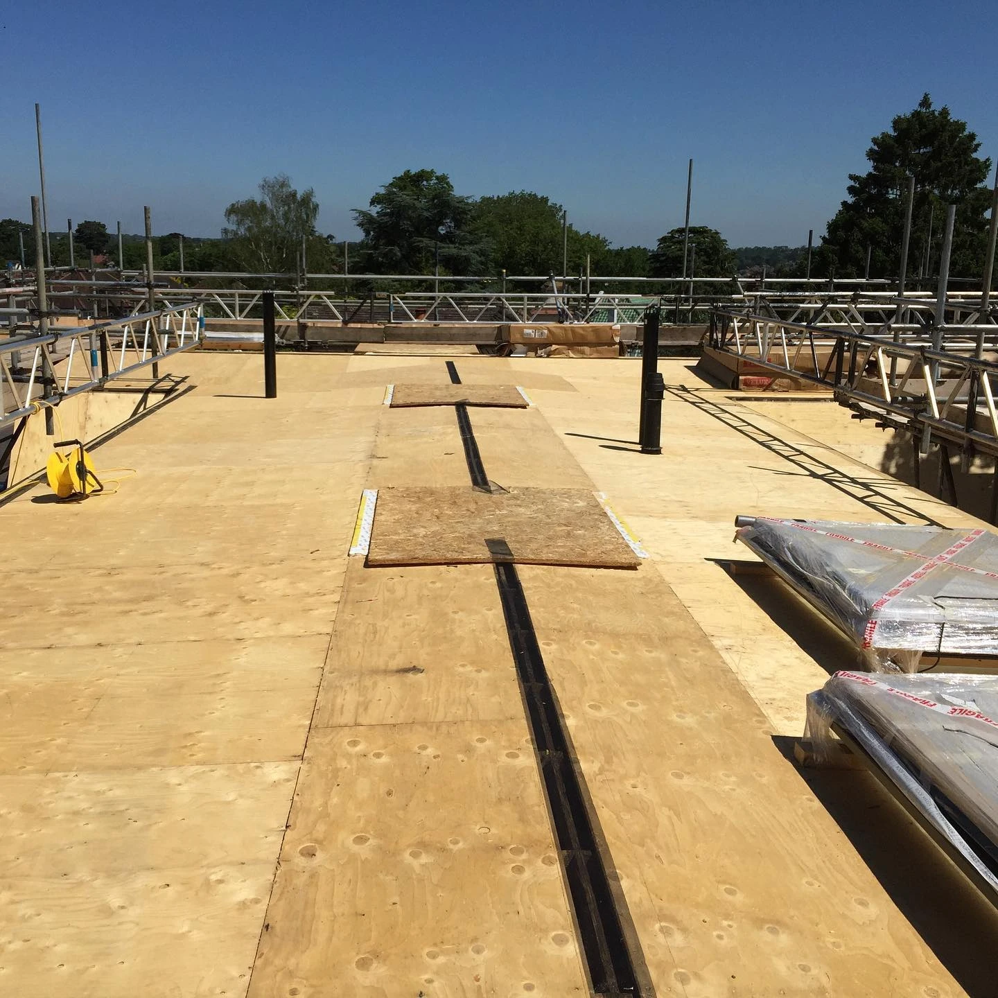
5. Bespoke ventilated roof components
Digitally designed and manufactured in our studio, the bespoke ventilated roof components have slots that enable the airflow to remove excess humidity from the building. Essential for a timber home! Once installed, the ventilated components were covered in a layer of plywood as a substrate for the zinc roof.

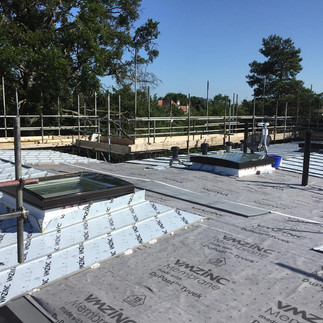
6. Standing seam zinc panels
The standing seams for the zinc panels were manufactured on site using a profiling machine and the panels were then installed on top of a second membrane.
The roof install meant that the rooftop yoga that our team on site had been doing every morning had to move to the lower floors!


Internal work, such as the bespoke oak and steel staircase is taking place while the external finishes (render and Equitone panelling) are completed. Stay tuned!
Thinking about building your dream home?
For more information and to find out whether we could build your home using the Facit Chassis™️ DFMA system, call the studio on 020 3034 0720 or info@facit-homes.com.


